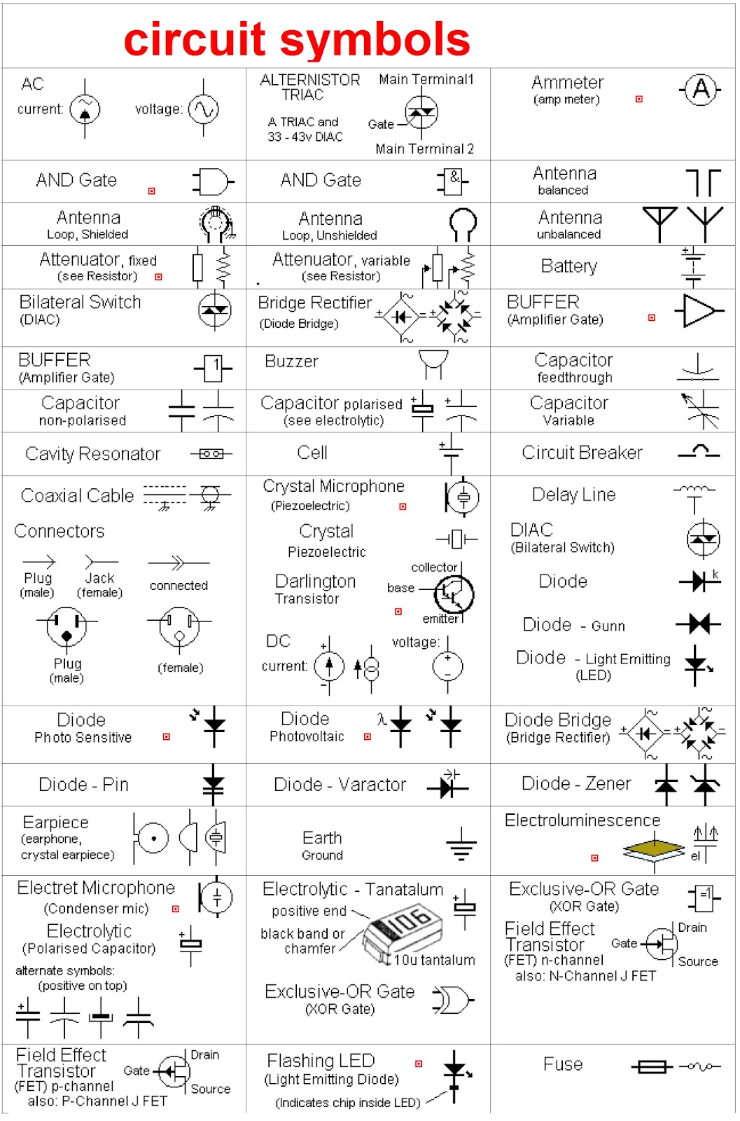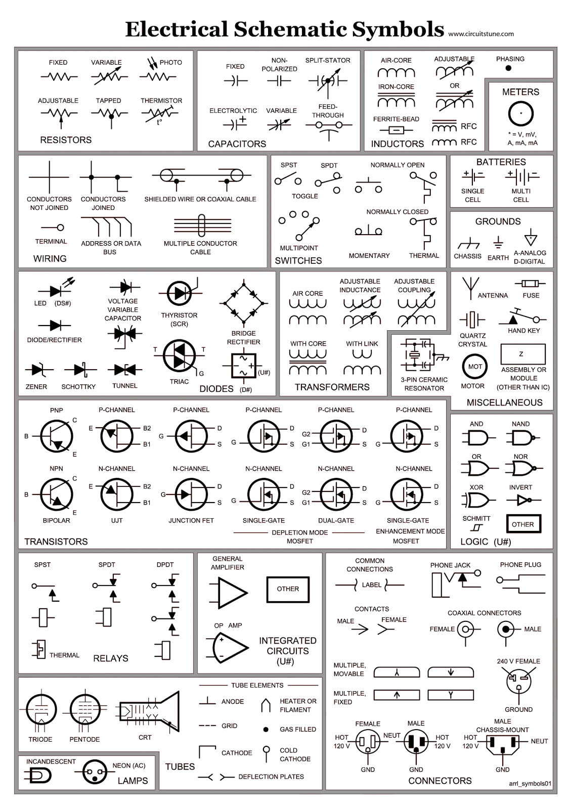
Ever stare at a circuit diagram and feel like you're deciphering ancient hieroglyphs? You're not alone. Those cryptic squiggles and circles, the seemingly random lines connecting them – they're not some secret code, but a universal language: electrical and electronic schematic symbols. And understanding them is key to unlocking the mysteries of electronics.
These symbols, like the words in a sentence, tell a story. They represent the various components within a circuit, from simple resistors and capacitors to complex microcontrollers and integrated circuits. They detail how these elements interact, how energy flows, and how information is processed. Imagine trying to build a house without blueprints. That’s essentially what designing electronics without schematic symbols would be like – chaotic and likely disastrous.
Schematic representations in electrical and electronic diagrams have a rich history, evolving alongside the technology they describe. Early diagrams were often crude, hand-drawn affairs, but as electronics became more sophisticated, so did the symbols used to represent them. Standardization efforts by organizations like the IEEE (Institute of Electrical and Electronics Engineers) and IEC (International Electrotechnical Commission) have led to a globally recognized set of symbols, making collaboration and communication between engineers seamless.
The primary issue surrounding electronic blueprint language isn't the symbols themselves, but their proper application and interpretation. Incorrectly used or misunderstood circuit design symbols can lead to faulty designs, malfunctioning devices, and even safety hazards. Hence, a solid grasp of these symbols is crucial for anyone working with electronic circuits, from hobbyists tinkering in their garages to professional engineers designing complex systems.
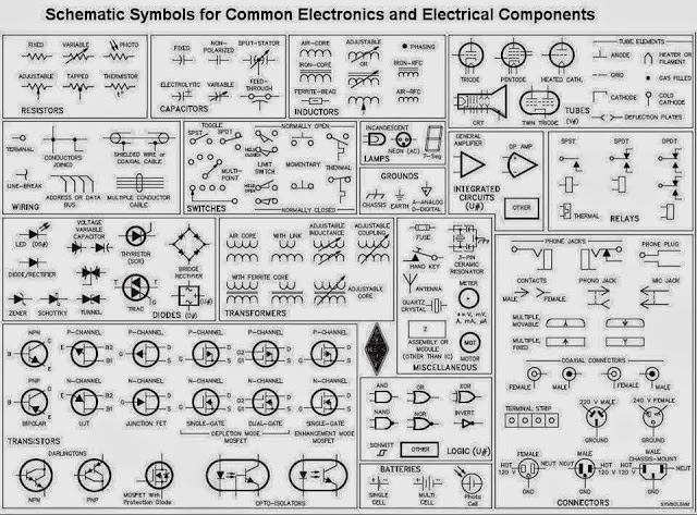
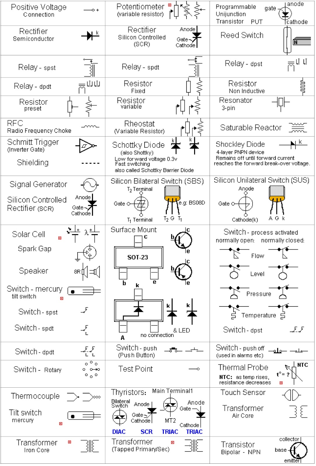
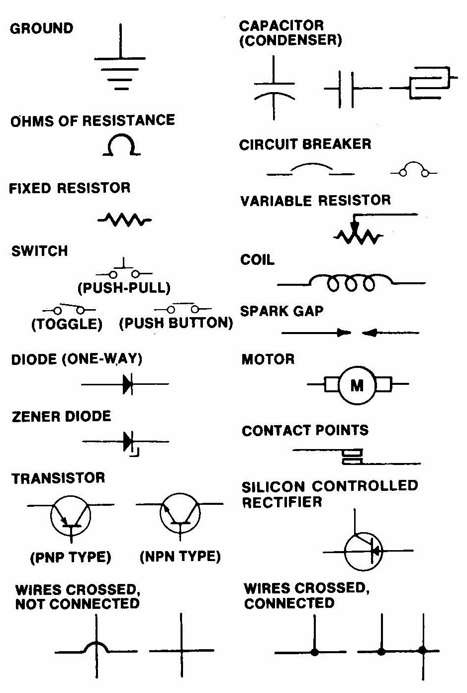
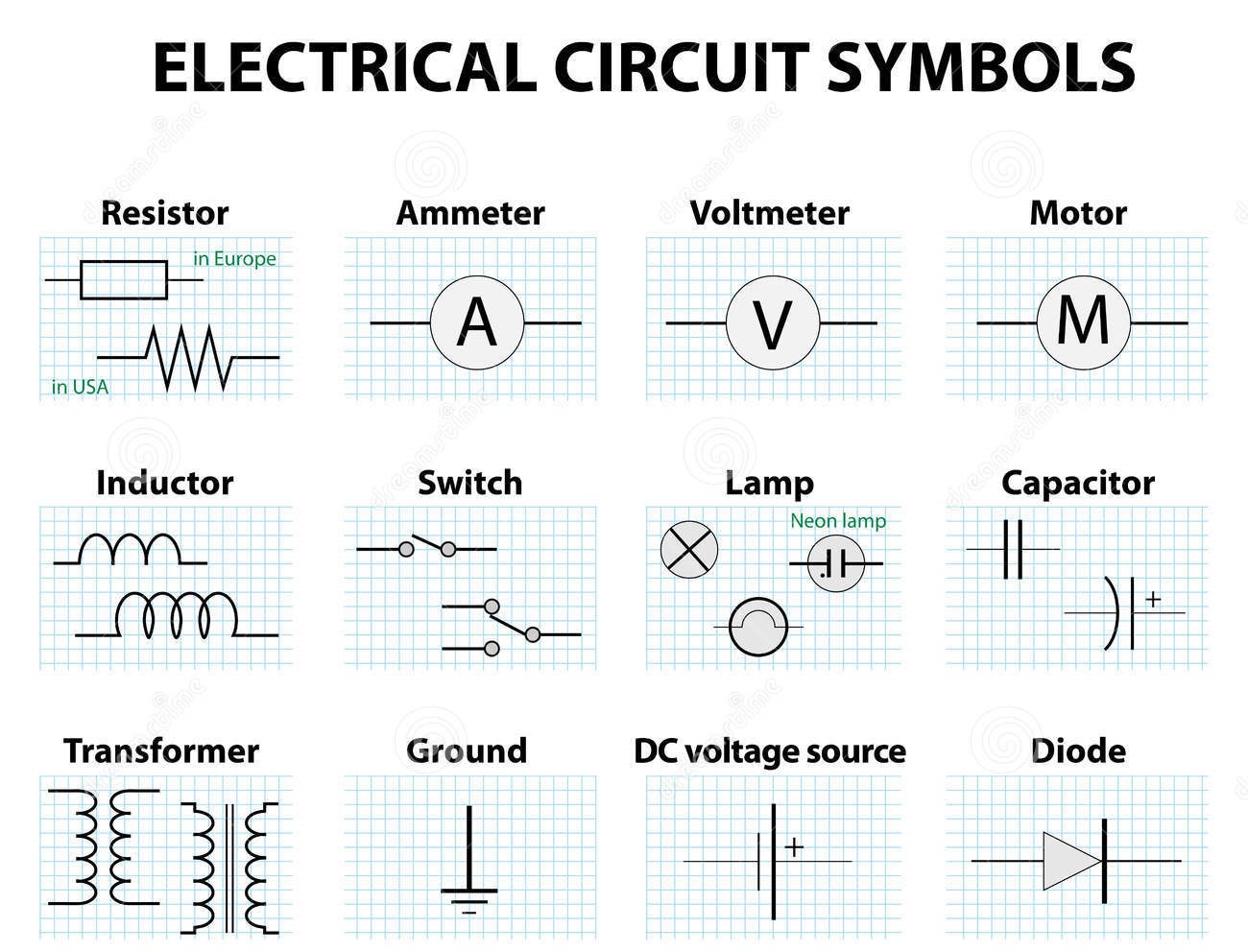
A resistor, for example, is represented by a zigzag line, symbolizing its function of restricting current flow. A capacitor, used to store electrical charge, is depicted as two parallel lines, reflecting its construction. These symbols aren't arbitrary; they often visually hint at the component's function or structure. Understanding these visual cues can accelerate the learning process.
One major benefit of standardized diagram representations is clarity. They offer a concise and universal way to represent complex circuits, making them easier to understand and analyze. This facilitates collaboration among engineers and technicians, regardless of their native language or background.
Another advantage is efficiency. Using symbolic diagrams allows engineers to design and troubleshoot circuits much faster than if they had to describe everything in words. Imagine explaining the wiring of a computer motherboard using only text – a daunting task, to say the least.
Furthermore, using electronic diagram notations enables simulation and analysis. Modern software tools can interpret these symbols, allowing engineers to simulate circuit behavior and identify potential problems before physically building anything. This saves time, resources, and prevents costly errors.
Understanding diagrams is essential. Start by learning basic components like resistors, capacitors, and inductors. Then, progress to more complex elements like transistors and integrated circuits. Numerous resources, including online tutorials, textbooks, and mobile apps, offer comprehensive symbol libraries and explanations.
Advantages and Disadvantages of Using Electrical Schematic Symbols
| Advantages | Disadvantages |
|---|---|
| Clarity and Universal Understanding | Requires Initial Learning and Practice |
| Efficient Design and Troubleshooting | Potential for Misinterpretation if not used correctly |
| Enables Simulation and Analysis | Can be overwhelming for highly complex circuits |
Best practices for schematic symbols: 1. Use standardized symbols. 2. Label components clearly. 3. Maintain consistency. 4. Keep diagrams clean and organized. 5. Use appropriate software tools.
Frequently asked questions: 1. What is a resistor symbol? 2. How is a capacitor represented? 3. What does a ground symbol look like? 4. How do I represent a diode? 5. What is the symbol for an inductor? 6. How do I interpret a transistor symbol? 7. What are the common logic gate symbols? 8. Where can I find a comprehensive list of electronic symbols?
Tips and tricks: Familiarize yourself with the IEC and IEEE standards. Use online resources and interactive simulators. Practice reading and drawing schematics regularly.
In conclusion, electrical and electronic schematic symbols are the bedrock of circuit design and analysis. They offer a powerful language for communicating complex ideas, enabling efficient design, troubleshooting, and collaboration. While there's an initial learning curve, mastering these symbols is an invaluable investment for anyone involved in electronics. Understanding these symbols opens up a world of possibilities, from designing simple circuits to developing complex electronic systems. So, embrace the challenge, dive in, and decode the matrix of electrical and electronic schematic symbols – you might just surprise yourself with what you can create.
Decoding the canine canvas pink raised skin bumps on dogs
Unlocking connection icebreakers for guys
Effortless elegance navigating the world of tall womens trousers
