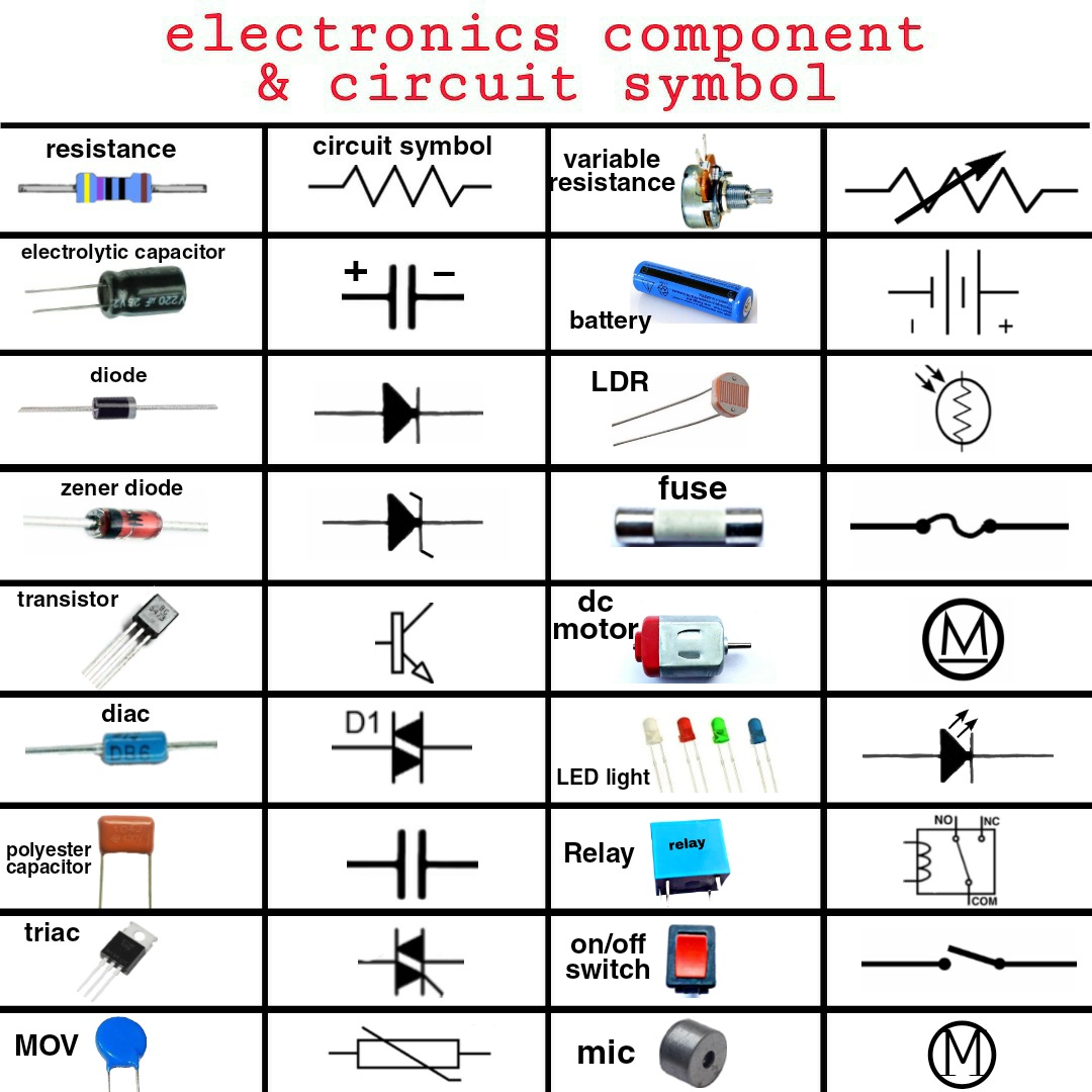
Imagine trying to assemble a complex piece of furniture without instructions. Frustrating, right? Similarly, navigating the world of electricity without understanding the language of its diagrams would be utterly chaotic. This is where electrical symbols come into play. These small, seemingly simple graphical representations are the building blocks of electrical communication, allowing engineers, electricians, and hobbyists alike to understand and build circuits efficiently and safely.
Electrical symbols, essentially a visual shorthand, represent various electrical and electronic components. They provide a universal language for depicting circuit layouts, simplifying complex systems into understandable diagrams. Think of them as the words in an electrical sentence, each carrying specific meaning and contributing to the overall message of the circuit’s function.
From the humble resistor to the powerful transformer, each component has its own designated symbol, meticulously designed for clarity and international recognition. Understanding these symbols is crucial for anyone working with electricity, whether designing a power grid or simply wiring a light switch. This intricate language of lines, circles, and squiggles forms the backbone of electrical engineering, allowing us to harness the power of electricity in a safe and controlled manner.
The history of electrical symbols is intertwined with the development of electricity itself. As scientists and inventors began to experiment with and understand electrical phenomena, the need for a standardized way to represent these concepts became clear. Early electrical diagrams were often crude and inconsistent, but over time, through collaboration and standardization efforts, a more universally recognized system emerged. Organizations like the International Electrotechnical Commission (IEC) played a vital role in establishing these standards, ensuring consistent interpretation across disciplines and geographical boundaries.
The significance of electrical symbols lies in their ability to facilitate communication and understanding. They allow complex electrical systems to be represented concisely and unambiguously, enabling engineers and technicians to design, analyze, troubleshoot, and maintain electrical systems efficiently. Without standardized symbols, the world of electrical engineering would be a confusing mess of custom diagrams and misinterpretations, hindering progress and increasing the risk of errors and accidents.
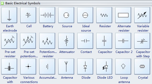
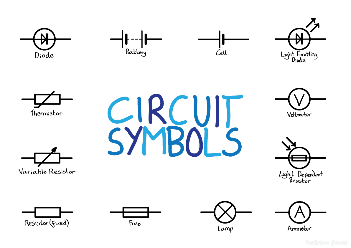
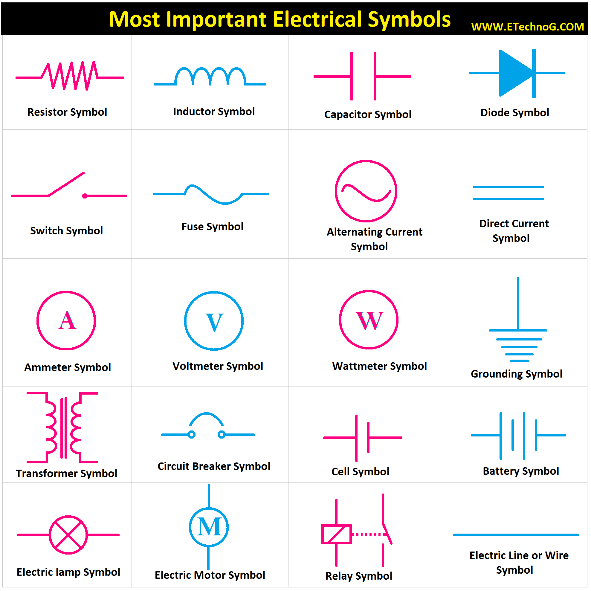
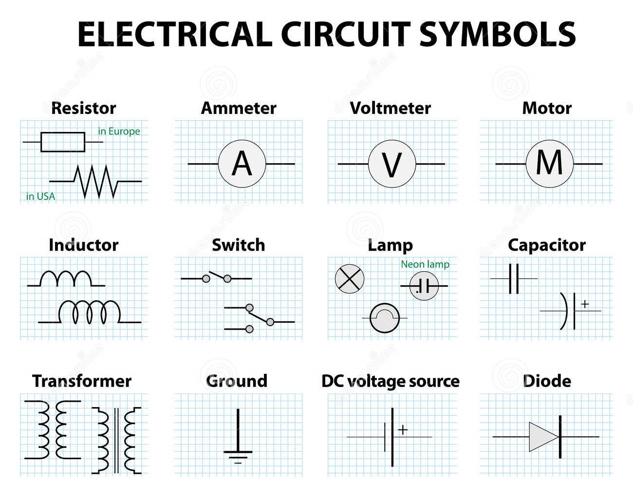
For instance, a battery is represented by two parallel lines, one longer than the other, symbolizing the positive and negative terminals. A resistor, which impedes the flow of current, is represented by a zigzag line. These seemingly simple depictions convey essential information about the component’s function within a circuit.
Three key benefits of using electrical symbols include improved communication, simplified design, and enhanced safety. Clear communication is fostered through the use of standardized symbols, ensuring that everyone involved understands the circuit's layout and functionality. Simplified design is achieved by allowing engineers to quickly sketch and analyze complex circuits without needing lengthy written descriptions. Enhanced safety is ensured by providing a clear and consistent way to represent potential hazards, preventing misinterpretations that could lead to accidents.
Advantages and Disadvantages of Standardized Electrical Symbols
| Advantages | Disadvantages |
|---|---|
| Universal understanding | Requires learning and memorization |
| Simplified circuit representation | Can be complex for extremely detailed circuits |
| Improved communication | Potential for misinterpretation if not used correctly |
Best Practices for Using Electrical Symbols:
1. Adhere to IEC standards.
2. Use consistent symbol sizes and orientations.
3. Clearly label all components.
4. Maintain neat and organized diagrams.
5. Double-check your work for accuracy.
Real-world examples include circuit diagrams for house wiring, electronic device schematics, industrial control systems, power grid diagrams, and automotive electrical systems. Each of these applications relies heavily on electrical symbols to convey critical information about the electrical connections and components involved.
Challenges related to electrical symbols include keeping up with evolving standards, ensuring accurate interpretation, and dealing with the sheer number of different symbols. Solutions include ongoing training and education, using software tools that incorporate the latest standards, and referring to comprehensive symbol libraries.
FAQs:
1. Where can I find a comprehensive list of electrical symbols? (Answer: IEC website, engineering textbooks)
2. What is the difference between an IEC symbol and an ANSI symbol? (Answer: Different standardization bodies)
3. How can I learn electrical symbols quickly? (Answer: Online resources, practice diagrams)
4. Are electrical symbols the same worldwide? (Answer: Largely standardized through IEC)
5. What software can I use to create electrical diagrams? (Answer: Various CAD software)
6. What are the most common electrical symbols? (Answer: Resistor, capacitor, inductor, battery, switch)
7. Why is it important to use standardized electrical symbols? (Answer: Clear communication, safety)
8. How are new electrical symbols developed? (Answer: Through standardization bodies like the IEC)
Tips and Tricks: Use flashcards, online quizzes, and practice drawing circuits to reinforce your understanding of electrical symbols.
In conclusion, electrical symbols and their names form the essential language of electrical engineering and related fields. Understanding these representations is paramount for effective communication, safe design practices, and efficient troubleshooting. From the simple light switch in your home to the complex power grids that supply our cities, electrical symbols are silently at work, facilitating the flow of electricity that powers our modern world. By mastering this language, we unlock the ability to design, build, and maintain the electrical systems that underpin our technologically advanced society. So, whether you're a seasoned engineer or a curious beginner, investing time in learning electrical symbols is a crucial step towards unlocking the mysteries of the electrical world and contributing to its continued evolution. Embrace this visual language, and you'll open doors to a deeper understanding of the technology that surrounds us.
Discover the world of printable cute drawings
Unlocking the secrets of pennsylvania state employee compensation
Strengthen your bond essential inquiries for your partner

