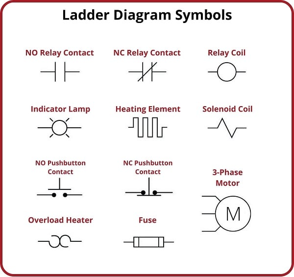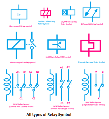
Ever wondered about those squiggly lines and rectangles on electrical diagrams? Chances are, you've encountered the IEC relay coil symbol, a fundamental element in control circuits. Understanding this seemingly simple symbol is crucial for anyone working with electrical systems, from seasoned engineers to budding technicians. It's the key to unlocking the power of relays, enabling automated control in countless applications.
The International Electrotechnical Commission (IEC) standard provides a universal language for electrical symbols, ensuring clear communication and minimizing misinterpretations across global projects. The relay coil symbol, specifically, represents the electromagnet that activates the relay. This electromagnet, when energized, creates a magnetic field that physically moves the relay's contacts, thereby switching electrical circuits on or off.
The history of the IEC relay coil symbol is intertwined with the development of relay technology itself. As relays evolved from simple electromagnetic switches to complex control devices, the need for standardized representation became apparent. The IEC stepped in to establish a consistent visual language, facilitating collaboration and ensuring clarity in circuit design.
The importance of the IEC standard, including the relay coil symbol, cannot be overstated. It promotes interoperability, allowing engineers worldwide to understand and work with each other's designs. This standardization minimizes errors, enhances safety, and streamlines the design and implementation of electrical control systems.
One of the main challenges associated with IEC relay coil symbols, and electrical symbols in general, is ensuring accurate interpretation. While the IEC standard provides clear guidelines, misinterpretations can still occur due to lack of familiarity or improper implementation. Proper training and adherence to the IEC standard are essential to avoid potential issues.
The IEC relay coil symbol typically consists of a rectangle, representing the coil itself, and a connected line or lines, which symbolize the coil terminals. Variations of the symbol may include additional elements to indicate specific coil properties, such as polarity or operating voltage.
Benefits of using standardized IEC relay coil symbols include improved communication among engineers, reduced design errors, and enhanced safety in electrical systems. For example, a technician troubleshooting a circuit in Germany can easily understand a diagram created by an engineer in Japan, thanks to the standardized symbols.
Implementing IEC relay coil symbols correctly involves using the appropriate symbol for the specific type of relay coil and ensuring its proper placement within the circuit diagram. Software tools for electrical design often include libraries of IEC symbols, making it easy to incorporate them into your designs.
Real-world examples of relay coils and their associated symbols can be found in various applications, including industrial automation, automotive control systems, and home appliances. Think of a washing machine's timer controlling the wash cycle or the automated lighting systems in a smart home. These systems often rely on relays with their respective coil symbols represented in the control circuits.
Advantages and Disadvantages of Standardized Relay Coil Symbols
| Advantages | Disadvantages |
|---|---|
| Improved communication and understanding | Requires familiarity with the IEC standard |
| Reduced design errors and misinterpretations | Potential for misinterpretation if not implemented correctly |
| Enhanced safety and reliability of electrical systems |
Frequently Asked Questions:
1. What does the IEC relay coil symbol represent? - The electromagnet that activates the relay.
2. Why is standardization important for relay coil symbols? - It ensures clear communication and minimizes errors.
3. What are some common variations of the relay coil symbol? - Symbols indicating polarity or operating voltage.
4. How can I learn more about IEC relay coil symbols? - Consult the IEC standard documentation or specialized electrical engineering resources.
5. Where can I find examples of IEC relay coil symbols in use? - In electrical diagrams for various applications, like industrial automation and home appliances.
6. What software can I use to draw IEC relay coil symbols? - Many electrical CAD software packages include libraries of IEC symbols.
7. What are some common challenges related to interpreting IEC symbols? - Lack of familiarity with the standard or incorrect implementation.
8. How can I avoid misinterpreting IEC relay coil symbols? - Proper training and adherence to the IEC standard.
Tips and tricks for working with IEC relay coil symbols include using reference guides, software libraries, and consulting with experienced engineers to ensure accurate representation and interpretation.
In conclusion, the IEC relay coil symbol is more than just a squiggle on a diagram. It's a fundamental element in the language of electrical control, representing a crucial component in countless applications. Understanding its meaning, history, and proper usage is essential for anyone working with electrical systems. By embracing the IEC standard and diligently applying its principles, we can ensure clear communication, minimize errors, and unlock the full potential of relay technology in a safe and efficient manner. The benefits of standardization, from improved design collaboration to enhanced safety, are far-reaching and contribute significantly to the advancement of electrical engineering. As technology continues to evolve, the IEC relay coil symbol will remain a cornerstone of electrical control, enabling innovation and driving progress in diverse fields. So, next time you see that seemingly simple symbol, remember its profound significance in the world of electrical engineering.
Unlock your design vision sherwin williams custom color guide
Decoding baby gripe water a new parents survival guide
Decoding the jaja al chile meme phenomenon


