Ever looked at a circuit diagram and felt like you were deciphering an alien language? You're not alone. Electronic schematic symbols are the building blocks of any circuit design, a visual shorthand that represents electronic components and their connections. Understanding these symbols is crucial for anyone working with electronics, from hobbyists building their first Arduino project to seasoned engineers designing complex systems. This guide will unlock the secrets of these symbols and empower you to navigate the world of electronics with confidence.
Electronic schematic symbols are standardized representations used in circuit diagrams. They provide a concise and universally understood way to depict the various components within an electronic system, such as resistors, capacitors, transistors, integrated circuits, and more. These symbolic representations allow engineers and technicians to communicate design ideas efficiently, troubleshoot circuits effectively, and document electronic systems accurately. Imagine trying to describe a complex circuit using only words – it would be a nightmare! Schematic symbols provide a visual language that simplifies this process immensely.
The history of electronic schematic symbols is intertwined with the development of electronics itself. As electronic circuits became more complex, the need for a standardized system of representation became evident. Early schematic diagrams were often hand-drawn and varied in style. Over time, organizations like the Institute of Electrical and Electronics Engineers (IEEE) and the International Electrotechnical Commission (IEC) developed and refined standards for electronic schematic symbols, leading to the consistent system we use today. Finding these symbols in a convenient PDF format has become essential for both learning and professional practice.
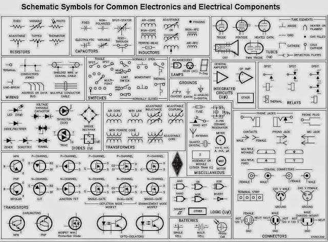
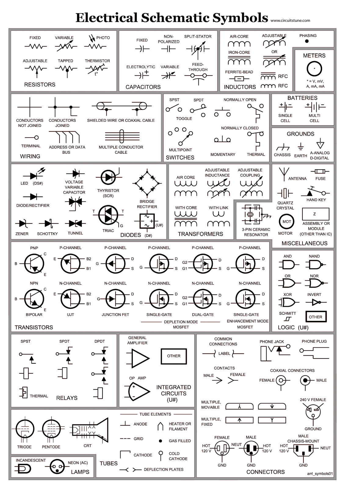
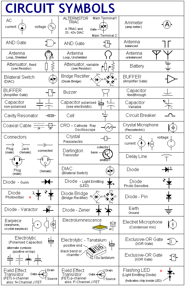
Why are electronic schematic diagrams and their associated symbol PDFs so important? Simply put, they are the blueprints of electronic systems. They facilitate communication, analysis, and troubleshooting. Without a clear schematic diagram, understanding and working with an electronic circuit becomes incredibly challenging. A downloadable schematic symbol PDF provides a quick reference guide, crucial for anyone learning or brushing up on their electronics knowledge. These PDFs often categorize symbols by function, making it easy to find the representation you need.
One of the main issues related to electronic schematic symbols is keeping up with the ever-evolving landscape of electronic components. New components are constantly being developed, each requiring its own unique symbol. Staying updated with the latest symbols and standards is essential for accurate circuit design and analysis. Fortunately, online resources and regularly updated electronic symbol PDFs make this task manageable.
Benefits of utilizing readily available schematic symbol PDFs include easy access to a comprehensive library of symbols, portability for on-the-go reference, and the ability to print and share diagrams effortlessly.
A step-by-step guide to understanding schematic diagrams would involve: 1. Identifying the components by their symbols. 2. Tracing the connections between components. 3. Understanding the flow of current and signals. 4. Analyzing the circuit's function based on the component interactions.
Advantages and Disadvantages of Using Schematic Symbol PDFs
| Advantages | Disadvantages |
|---|---|
| Easy access and portability | Can become outdated if not regularly updated |
| Comprehensive symbol library | Requires a PDF reader |
| Printable and shareable | May not cover highly specialized symbols |
Best practices for using schematic symbols include adhering to established standards, using clear and concise labels, maintaining consistent symbol orientation, and ensuring the diagram is well-organized and easy to read.
Challenges in working with schematic symbols might include difficulty interpreting complex diagrams, staying updated with new symbols, and ensuring accuracy in large and intricate designs. Solutions include utilizing software tools for schematic capture, referring to comprehensive symbol libraries, and employing a systematic approach to diagram creation and analysis.
FAQ: What is a resistor symbol? What does a capacitor symbol look like? What is the symbol for a diode? How do I read a schematic diagram? Where can I find a reliable electronic schematic symbol PDF? What are the basic electronic symbols? How do I identify integrated circuit symbols? What software can I use to create schematic diagrams?
Tips and tricks: Use color-coding to highlight different sections of your circuit. Organize your schematic diagrams logically. Annotate your diagrams with relevant notes and explanations.
In conclusion, understanding electronic schematic symbols is fundamental for anyone involved in electronics. From simple circuits to complex systems, these symbols provide a universal language for communicating design ideas, troubleshooting problems, and documenting electronic creations. Leveraging readily available resources like electronic schematic symbols PDFs allows for efficient learning and effective application of this crucial knowledge. By mastering this symbolic language, you unlock the power to design, analyze, and build the electronic devices of tomorrow. Embrace the challenge, explore the resources available, and embark on your journey into the fascinating world of electronics.
Uncovering the mystery of gingers hues
Decoding benjamin moores cedar grove the ultimate guide
Hypnosis king in another world free novel trend


.jpg)
